
Metal-faced pu wall sandwich panels installation process
In the construction industry, metal-faced PU wall sandwich panels have become the preferred material for exterior walls and partitions in industrial plants, logistics warehouses, commercial buildings, and residential buildings due to their lightweight, high-strength, thermal insulation, fire and moisture resistance, and easy installation.
However, the installation quality of PU sandwich panels directly affects the durability, energy efficiency, and safety of a building. This article will systematically outline the standardized installation process for metal-faced PU wall sandwich panels based on international building codes (such as ISO 6946 Insulation Material Standard and ASTM D3767 Sandwich Panel Test Method) and practical experience from different climate zones around the world (frigid, tropical, and humid regions), providing a replicable guide for users worldwide.
I. Core Pre-Installation Preparations
1. Material and Tool Verification
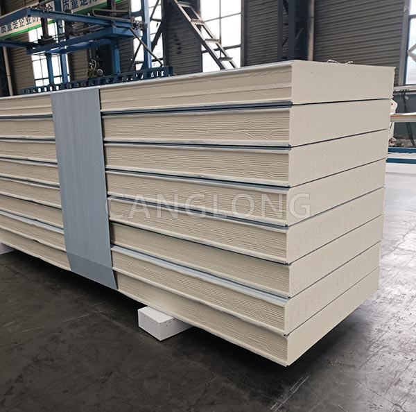
Panel Verification: Verify that the specifications of the metal-faced PU wall sandwich panels (typically 50-200mm thick, with 0.5-1.2mm galvanized steel or aluminum-magnesium-manganese alloy panels commonly used), fire rating (must comply with local fire regulations, such as EU EN 13501-1 B-s1,d0 and US UL 263), and thermal conductivity (typical value for PU core material: 0.022-0.028 W/(m·K)) are consistent with design requirements.
Accessories: Verify that the supporting keels (galvanized steel or aluminum alloy, recommended spacing: 400-600mm), self-tapping screws (countersunk head, length ≥ panel thickness + keel thickness), sealant (weather-resistant silicone sealant, adapted to local temperature and humidity), and brackets/fixtures (rust-proofed) are complete.
Tool List: Required: Laser level (accuracy ±0.5mm/m), electric drill (with 4-6mm drill bit), tape measure (over 5m), wallpaper cutter (for cutting core material), rubber hammer (for adjusting panel seams), and caulking gun (pneumatic/electric).
2. Site Condition Assessment
Base wall surface: Must be flat, dry (moisture content ≤ 8%), and free of oil stains and hollows. If the wall is a concrete wall, remove loose dust. If the structure is a lightweight steel structure, confirm the purlin spacing (≤ 1.2m) and load-bearing capacity (single-point load ≥ 50kg).
Climate Adaptation:
- Cold/High-Altitude Areas: Focus on checking the freeze-thaw resistance of the panels (must pass -40°C freeze-thaw cycle testing). A 5-10mm expansion joint should be left between the studs and the wall to prevent cracking due to thermal expansion and contraction.
- For tropical/humid regions: Use salt-spray-resistant aluminum-magnesium-manganese alloy panels (salt spray test ≥ 1000 hours), and add an additional waterproofing layer (such as butyl tape + weather-resistant adhesive) to the joints.
- For high-seismic zones: Use L-shaped or T-shaped reinforcements for the keels, shorten the fixing spacing to 300mm, and control the panel gap width to 8-10mm (fill with elastic sealant to enhance seismic cushioning).

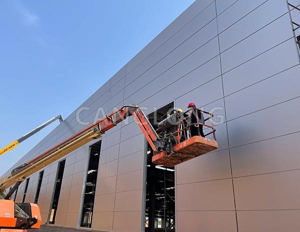
II. Standardized Installation Process
Step 1: Measuring and Laying Out
Based on the building axis, use a laser level to draw horizontal control lines (with an error of ≤ 2mm) and vertical control lines (one every 3m). Mark the keel installation location (150-200mm from the wall edge).
Tip: Avoid measuring during midday heat in tropical regions (thermal expansion of the steel may cause errors). In cold regions, work should be performed when the daytime temperature is ≥ 5°C (low temperatures affect adhesive curing).
Step 2: Install the purlins
Secure the primary purlins (vertically) along the control lines, connecting them with expansion bolts (spacing ≤ 600mm) or welding (on the steel base). Secondary purlins (horizontally) are perpendicular to the primary purlins and secured with angle brackets to form a primary and secondary grid.
Key Details: A 3-5mm gap should be maintained between the purlin surface and the back of the panels (for filling insulation or adjusting panel gaps). In humid areas, a moisture-proof membrane (PE film, with an overlap of ≥ 100mm) should be installed between the purlins and the base.
Step 3: Secure the Sandwich Panels
First Panel Positioning: Select a building corner or a primary viewpoint as the first panel installation point. Use a rubber hammer to gently tap the panel to ensure a tight fit (gap ≤ 2mm). Self-tapping screws should be spaced ≤ 300mm along the panel length and ≤ 200mm across the panel width. The screws should penetrate the panel and penetrate the purlin 1-2mm.
Splicing Multiple Panels: When splicing adjacent panels horizontally, align the tongue-and-groove (male and female grooves) and allow 8-10mm (in cold/humid regions) or 5-8mm (in temperate regions) for the joint. When splicing vertically, stagger the joints, with a horizontal offset of ≥300mm between adjacent panels to prevent concentrated thermal bridges.
Suitability: In high wind pressure areas (coastal typhoon zones), add metal battens (aluminum alloy, thickness ≥1.5mm) and secure with self-tapping screws spaced ≤200mm apart. In seismic zones, insert rubber gaskets (Shore hardness 60-70HA) into the panel joints to enhance flexible connections.
Step 4: Joint Preparation
Sealant Filling: After cleaning the panel joints, first fill with a foam rod (diameter ≥1.2 times the joint width), then apply weather-resistant silicone sealant (3-5mm thick, width ≥2 times the joint thickness). Ensure a continuous and smooth joint (no bubbles or breakage).
Special Area Reinforcement: An additional waterproofing layer (such as waterproofing membrane + sealant) should be applied around door and window openings. Specialized metal corner guards (aluminum alloy, thickness ≥ 1mm) should be used at corners and fully bonded to the panel adhesive (polyurethane adhesive).
Step 5: Final Inspection
Appearance Inspection: Check the panel surface for flatness (using a 2m straightedge, tolerance ≤ 3mm), even joints, and any loose or missing screws.
Functional Testing: In cold regions, an airtightness test can be performed (penetration ≤ 0.5 m³/(h·m) under a pressure differential of 50 Pa). In humid regions, a water spray test can be performed to verify waterproofing. No moisture marks should be observed on the wall for 2 hours.
Step 6: Documentation
Record the installation date, panel batch, keel specifications, adhesive type, and photos of key details to create an “Installation Acceptance Report” to facilitate future maintenance and quickly identify material parameters in the event of local damage.
III. Common User Misconceptions and Pitfalls
Myth 1: Thicker panels are better
PU core material density (≥40kg/m³) is more critical than thickness. Excessive thickness may increase thermal conductivity, while excessive density closes the cells, negatively impacting insulation. Select an appropriate thickness based on local energy-saving standards (such as EU EPBD and China GB 50189).
Myth 2: Neglecting substrate preparation
An uneven substrate will result in uneven stress on the panels, potentially leading to cracking over time. It is recommended to use gypsum board or calcium silicate board (thickness ≤ 15mm) for leveling and then secure with studs.
Myth 3: Using any sealant is fine
Ordinary white glue cannot withstand UV and temperature fluctuations. Weather-resistant silicone adhesive (compliant with ASTM C920) is essential. Especially in tropical or high-UV regions, choose a non-yellowing type (containing hindered amine light stabilizers).

Conclusion
Installing metal-faced PU wall sandwich panels are not a simple process of splicing; it involves a multi-dimensional system involving material compatibility, climate adaptability, and structural safety. Users should adjust their processes based on local conditions (climate, seismic intensity, and building codes), and prioritize professional construction teams with international certifications (such as CE, UL, and GB/T 23932). Only in this way can the efficiency, durability, and cost-effectiveness of the construction process be maximized, injecting lasting vitality into the building.